


Power & Propulsion Design inc. Batteries & Fuel Cells
With the increasing demands from regulators to improve the efficiencies and decrease the GHG emissions of vessels across the marine industry along with further focussed pressures from within specific marine market sectors, many owners and operators are looking at the option of integrating clean fuel and energy storage technologies to reduce or eliminate emissions from the generation of power on their vessels.
These solutions can vary from all-electric battery powered short range vessels with repeated operational profiles and appropriate shore charging facilities like in-land waterway or coastal ferries to longer range vessels such as wind farm crew transfer vessels using a combination of clean technologies like batteries and fuel cells along with high efficiency diesel engines in a hybrid topology.
These types of systems provide challenges for supply of solutions to both new and existing vessels in terms of selection of the correct technology to meet the operational profiles of the vessel along with meeting class regulations for safe operation and dependability. The principal challenges involve the physical integration of the new equipment when considering the spatial and weight limitations of a vessel’s design along with the additional safety and support services required and the general cost of implementing such solutions.
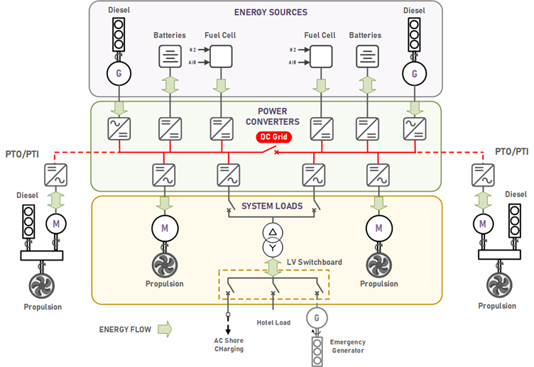
Figure 1: Example of System Topology
The general topology illustration above identifies the different elements that in various combinations can be developed to produce a hybrid electric power and propulsion solution for a vessel. Each element is a sub-system that can produce energy, consume energy or both.
Each sub-system connects to a common DC Grid through a dedicated power converter. In the case of the power producing sub-systems these converters allow the energy sources to produce power over a range of either variable AC or DC voltages whilst maintaining the DC Grid voltage at a fixed level.
The power converters of the consumers then develop either a 3 phase AC Voltage - variable in the case of the propulsion motor and fixed for the hotel / auxiliary load switchboard - or a variable DC voltage for example to start the fuel cell or charge the battery energy storage system.
Energy Sources
The inclusion, sizing and usage of these energy sources depends on the operational requirements of the vessel and in the cases of the batteries and fuel cells the availability of charging facilities and clean fuels.
Each energy source has their own limitations whether it be in terms of size, capacity, and response / performance. In addition to this there are the complexities of vessel integration, safety, size, weight, and cost. The overall system design is in many cases a compromise that provides increased efficiencies and reduced emissions with both a manageable cost and weight.
The typical types of energy sources integrated into these systems include:
- Diesel Engine
This is the traditional source of power which can be optimised in a DC Grid application to provide power over its most efficient speed range therefore minimising emissions. The performance of diesel engines has been sufficient to meet the operational requirements of the most demanding vessels albeit with sufficient parallel connected capacity to meet the need of high transient loads - Battery Energy Storage Systems
In certain cases, like short distance passenger ferries battery storage systems can provide the sole source of power on a vessel where the sizing of the batteries must consider the storage capacity for the required range and the charging / discharging rates needed to meet a defined schedule. In addition to this, batteries can be used in conjunction with diesel engines to provide a peak shaving function to mitigate the stresses on diesel engines during periods of high load fluctuations such as operating in high sea state conditions. - Fuel Cells
Fuel Cells typically provide base load power and often have limitations in both speed of response during operation and start-up and their overall flexibility due to a need to provide a minimum level of power. They will always require a secondary source of power to provide both the power needed to start them as well as meet the needs of transient loads on the vessel. - SuperCapacitors
Supercapacitors offer limited storage capacity but very high charge and discharge rates which in some cases may help with the sizing of the overall energy storage system in that it can help mitigate any very short-term requirements for handling high load fluctuations without having to oversize the battery.
Power Converters
At the heart of a DC grid solution are the power converters. The power converters are used to harness the power produced by the respective energy sources and control the power delivered to the load. In the case of the energy sources, they will provide the load sharing functionality and in general will provide the control of the amount and direction of energy flow into their connected sub-system. In general, the power converters are all the same devices (size dependent) with specific firmware depending on the function. In the context of a hybrid electric power and propulsion system power converters provide the following functions.
- Active Front End Converter
An active front end allows connection of an AC power source to the DC Grid. In the hybrid power and propulsion system application it typically acts as the power converter interface between a diesel generator and the DC Grid. In the case of the Diesel Generator the AFE will synchronise to the supply voltage produced by the generator and import power from it to the DC Grid. When connected in parallel with other energy sources the power converter can typically provide a droop characteristic that helps to share the load.
When connected to a Diesel Generator the active front end function allows optimisation of the power produced by the diesel engine by allowing it to run at a variable speed and frequency to produce power over its most efficient operating range rather than constraining it to run at a fixed speed for direct fixed frequency AC power generation.
AFE’s can also be used to provide an interface to an AC shore connection to provide the necessary power to the DC Grid for charging any connected battery energy storage system. - Micro-Grid Converter
The micro-grid converter meets the need for generating a fixed voltage and frequency power source for any auxiliary or hotel loads. It can produce a 3ph voltage supply in either an island mode (i.e., sole producer of system voltage) or synchronise to an existing supply and provide a parallel source of hotel load power. - DC: DC Converter
This a converter used to provide control of power / energy flow between a fixed voltage on the DC Grid and a variable DC voltage produced by the energy storage systems or fuel cells. - Inverter
The inverter’s main function is to control the speed of the electric motor driving the main propulsion.
In specific applications where an electric motor provides propulsion power in parallel to a directly driven diesel engine the inverter can perform a Power Take Off (PTO) / shaft generator function where it harvests power from the main engine to supply the DC grid, providing energy to the hotel load and the potential for charging any integrated energy storage systems.
In addition to this the inverter can enable the electric motor to provide additional propulsive to that of the diesel engine with a Power Take In (PTI) operating mode.
System Integration
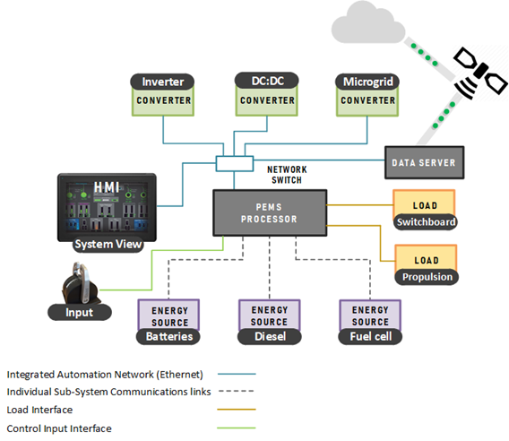
All the energy producing, and load consumer sub-systems must be integrated into a supervisory control system that monitors the health of the individual sub-systems and optimises the system configuration by selecting the numbers of connected energy sources and their respective functions to meet the operational needs of the vessel.
This control system – called the Power and Energy Management System (PEMS) – will also ensure that limitations and energy flow restrictions are imposed on the power converters to make certain that the correct start-up sequence and operational running requirements are managed for each integrated sub-system.
The PEMS is an extension to a traditional Power Management System with the additional requirement to prioritise the connected sources based on their respective availability and active capacity, existing or predicted power requirements of the vessel and the need to limit emissions and optimise efficiency whilst ensuring where necessary load consumption is limited to prevent blackouts.
Typically, diesel generators, fuel cell and energy storage systems will have their own management systems and these along with their respective power converters are connected to the PEMS over communications interfaces with the power converters controlling the active energy being imported from their respective energy source within the restrictions imposed by the PEMS,
In all cases visibility of the operational status and energy consumption of the full system is made available through dedicated operator interfaces with data also being made available to other vessel systems and in some cases through secure remote access
System Design and Class Approvals
Vessels with these types of electric or hybrid power and propulsion systems will have to get class approval before entering service. As the technologies are new and the class societies are building up their expertise with these systems it is always advisable to engage with their respective design teams at an early stage in the design approvals process in order minimise wasted effort and any delays in entering service.
Vessels of this type may be given a specific class notation e.g., Hybrid + which indicates that the vessel’s design has safely integrated one or more of the energy sources described in compliance with the regulations which also cover requirements for the following:
- Ventilation
- Gas detection
- Fire Suppression
- Cooling and temperature monitoring
- Machinery space requirements
In addition to that there are the requirements for dependability based on inherent redundancy in the design of the system to mitigate the effects of the loss of any part of the overall system. An example of this would be an RP (2,50%) which has two identical half systems where the loss of any one sub-system would result in a maximum of 50% loss in propulsive power – an example of this type of system is illustrated in Figure 1.
When considering the needs for redundancy in conjunction with the needs for efficiency, system design will often look at connecting the two half systems at the DC Grid level. In these cases, an overall consideration must be given to the short circuit capacity of the system and a rapid response to fault isolation to prevent a complete vessel blackout. The development of high-speed DC breakers for these applications have enabled this more flexible approach to system design with the result that as more of these systems are installed the more robust and effective, they are becoming.
Many vessel designs have unique operational profiles and there are always several options for potential solutions both in terms of system topology and technology. Marine Zero can help you establish the overall system requirements, give expert guidance on suitable solutions and the best technology fit for the specific vessel and manage the design approvals process with the designated class society.